Nagambie Transfer Station
Client: Strathbogie Shire Council
Location: Nagambie Transfer Station - 854 McDonalds, Nagambie, 3608
Project: Design and Construct of New Waste Bin Bay
Contract: Design and Construct
Project Value: $125,000
Construction Period: July 2023 to December 2023
Project Overview
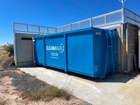
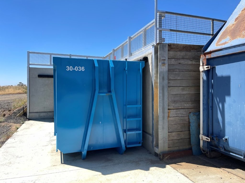
Civilvic was engaged by Strathbogie Shire Council to design and construct a new waste transfer bin bay at the Nagambie Transfer Station. The works formed part of Council's upgrade of its regional waste facilities, funded through the Victorian Government's Transfer Station Upgrade Fund – Round 2, and were undertaken within an operational transfer station while maintaining safe public access during scheduled operating days.
Council's project brief provided an aerial photograph identifying the proposed location of the new bin bay within a vacant embankment area immediately south of the two existing bin bays. The new facility was designed to complement the existing bin bay arrangement already operating on site. The new retaining wall has a clear height of approximately 2.8 metres and an overall length of approximately 7 metres.
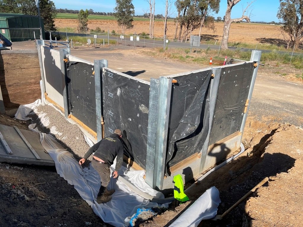
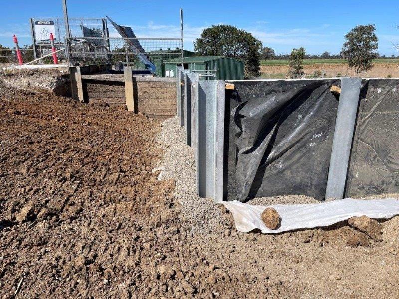
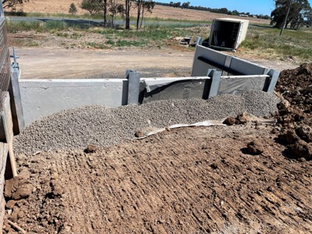
Civilvic designed the new retaining wall to incorporate bored concrete piers with structural steel columns as the vertical supports. Reinforced concrete tilt-up panels were cast horizontally on site and subsequently lifted into position between the supporting columns to form the retaining wall. Concrete panels were selected in place of timber sleepers to provide improved durability, reduced long-term maintenance and a consistent finished surface.
Related Civilvic Drawings
Retaining Wall Concept Plan & Elevation
Geotechnical Investigation
GTS Geotechnical Testing Services were engaged to undertake a geotechnical site investigation to assess the subsurface conditions and provide foundation design parameters for the proposed retaining wall.
Two boreholes were drilled to depths of 4.0 metres and 4.5 metres respectively. The investigation encountered high-plasticity silty clay, generally described as brown to pale grey and firm to very stiff. The site was classified as Class P due to the depth of uncontrolled fill exceeding 0.4 metres.
Design
Concept Design
Civilvic commenced the design process by undertaking detailed site measurements and preparing a new set of project drawings, including property boundary offsets and site levels, together with plans and elevations of the proposed retaining wall and concrete ground slabs.
The concept drawings were issued to Council for review and approval. DSL Consulting Engineers were subsequently engaged to develop the structural design using Civilvic's concept drawings and to provide structural drawings, engineering computations and certification as required for the building permit.
Local Building Surveyor Sam Verrocchi was engaged to issue the building permit and undertake the required building inspections throughout construction.
Related Civilvic Drawings
Retaining Elevation Section & Details
Final Design
DSL Consulting Engineers' final structural design specified a bored concrete pier and structural steel column retaining wall system, with the horizontal retaining wall members to comprise either precast concrete wall panels or precast concrete sleepers.
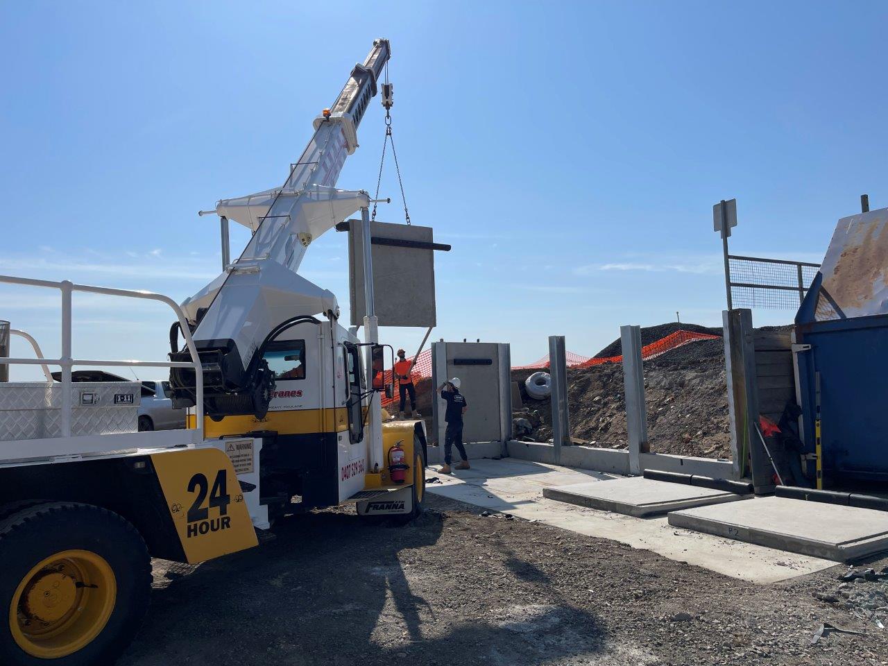
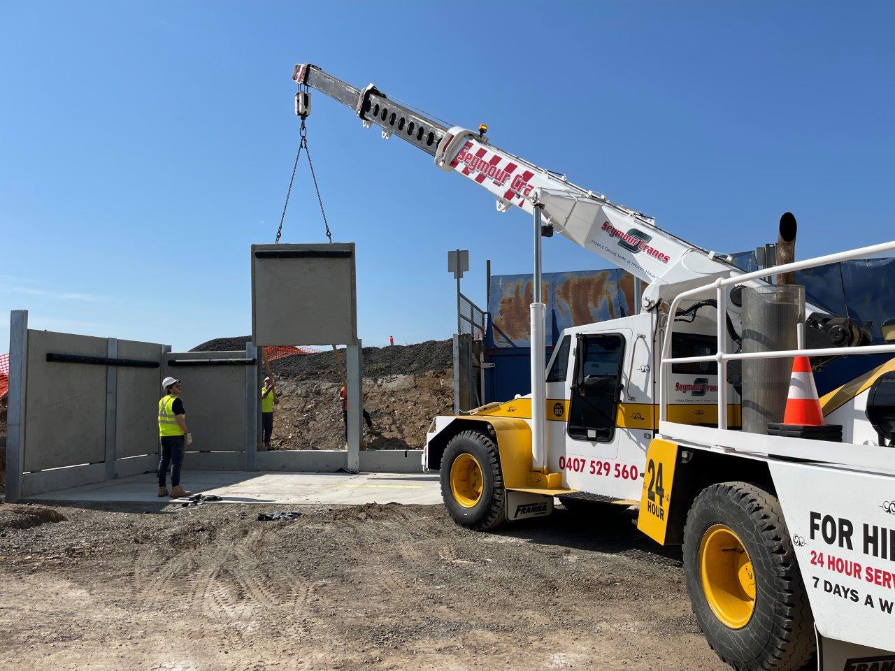
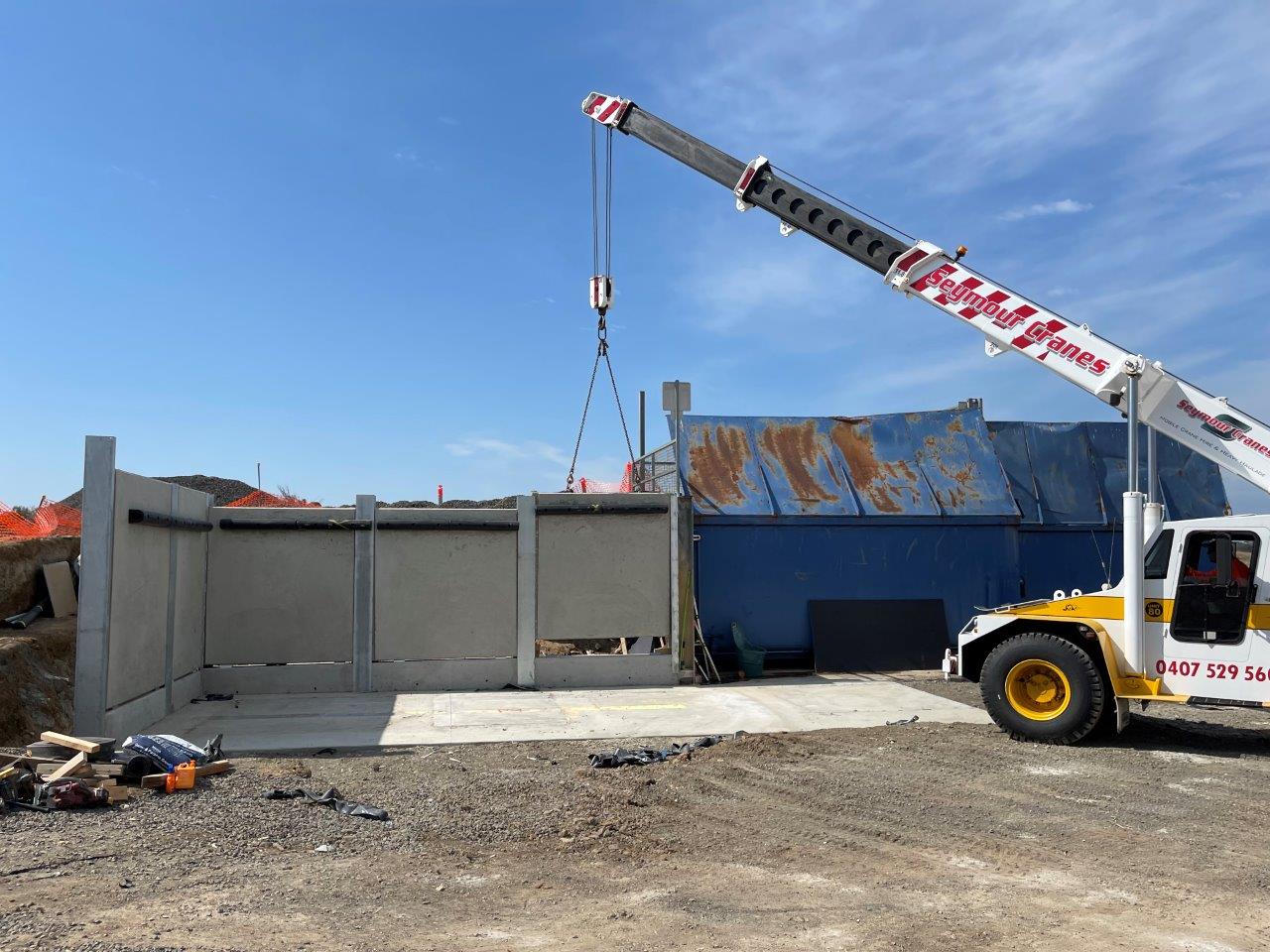
Civilvic selected reinforced concrete wall panels as the preferred solution. Panels were cast horizontally on site by Civilvic's concrete contractor. Local crane contractor Seymour Crane Service was engaged to lift the panels and install them into their final position between the structural steel columns.
Related Civilvic Drawings
DSL Consulting Engineers Structural Drawings
Construction
Site Excavation
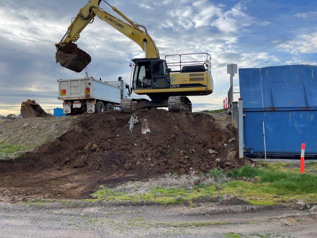
A local excavation contractor equipped with a 30-tonne excavator was engaged to undertake the site clearing and bulk excavation works. A section of the adjoining steel and timber retaining wall was demolished to provide sufficient space for construction of the new bin bay. The existing embankment was excavated, with the base then levelled and compacted to establish the required building envelope for the new retaining wall and bin bay facility.
Bored Piers & Steel Column Installation
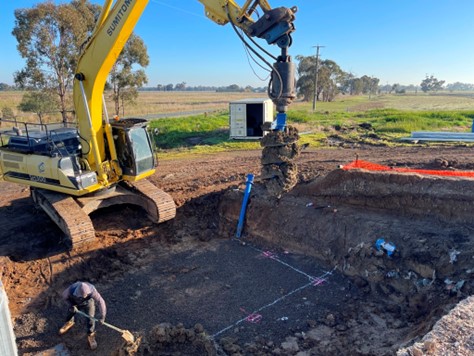
Following completion of the earthworks, the same 30-tonne excavator fitted with an auger attachment was used to drill 800 mm diameter bored pier holes to a depth of 4 metres.
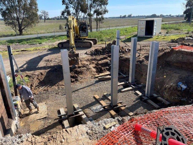
The excavator, fitted with a vertical lifting clamp attachment, was then used to lift and lower the structural steel columns into the bored pier holes. The columns were raised to the required height and temporarily supported using steel beam clamps to prevent them from lowering into the holes. Each column was then accurately aligned and plumbed before concrete was poured into the bored pier holes to permanently secure the columns in position.
Related Civilvic Drawings
Column Set_Out Plan & Elevations
Concrete Wall Upstand (Plinth)
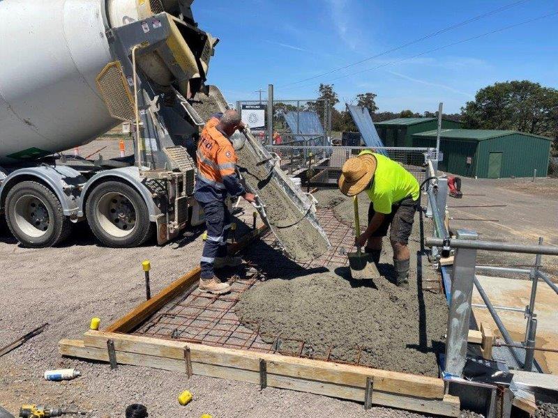
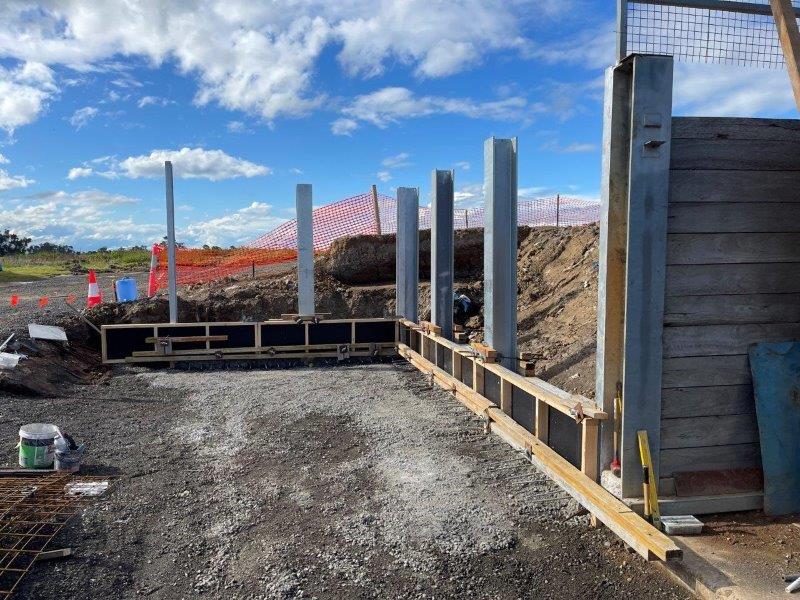
A reinforced concrete upstand was constructed between the structural steel columns. The upstand was constructed to a consistent level, providing a strong and level bearing surface for installation of the precast concrete wall panels. Reinforcement starter bars were cast into the upstand and projected from its base for subsequent incorporation into the reinforced concrete ground slab, providing a robust structural connection between the upstand and slab.
Related Civilvic Drawings
Plinth Rebar Elevation & Precast Dowel Plan
Ground Slab & Cast-In Skid Plates
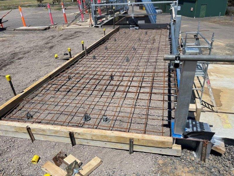
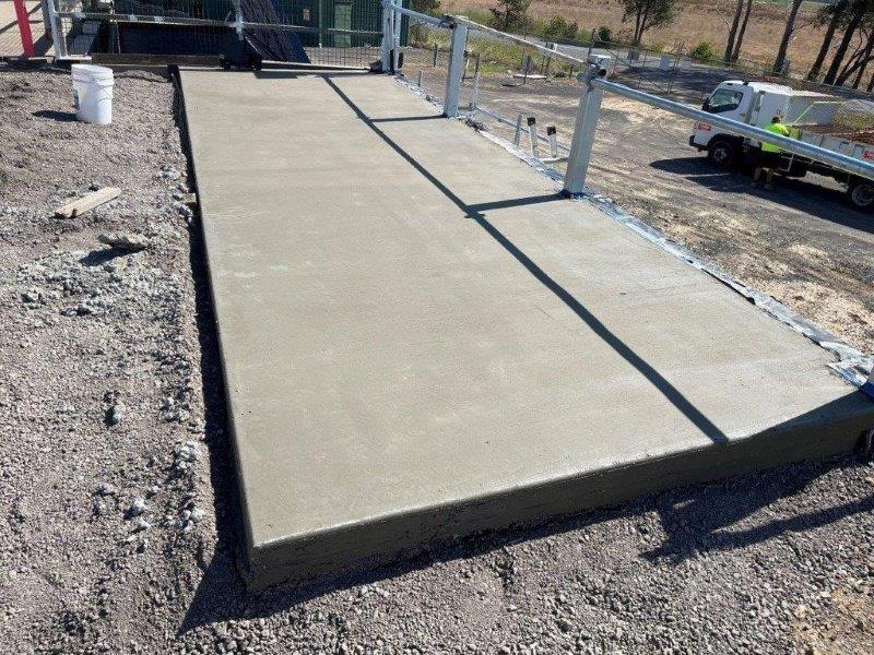
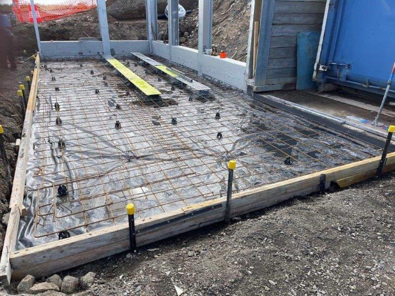
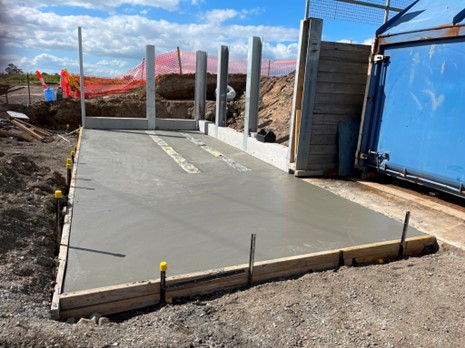
The reinforced concrete ground slab measures approximately 10 m long × 3.5 m wide × 200 mm thick and incorporates two cast-in steel skid plates. The steel plates provide a durable sliding surface for the bins during loading and unloading operations, reducing abrasion and wear to the concrete slab.
Related Civilvic Drawings
Concrete Ground Slab Re-bar Schedule
Skid Plate Set-Out Plan & Shop Drawing
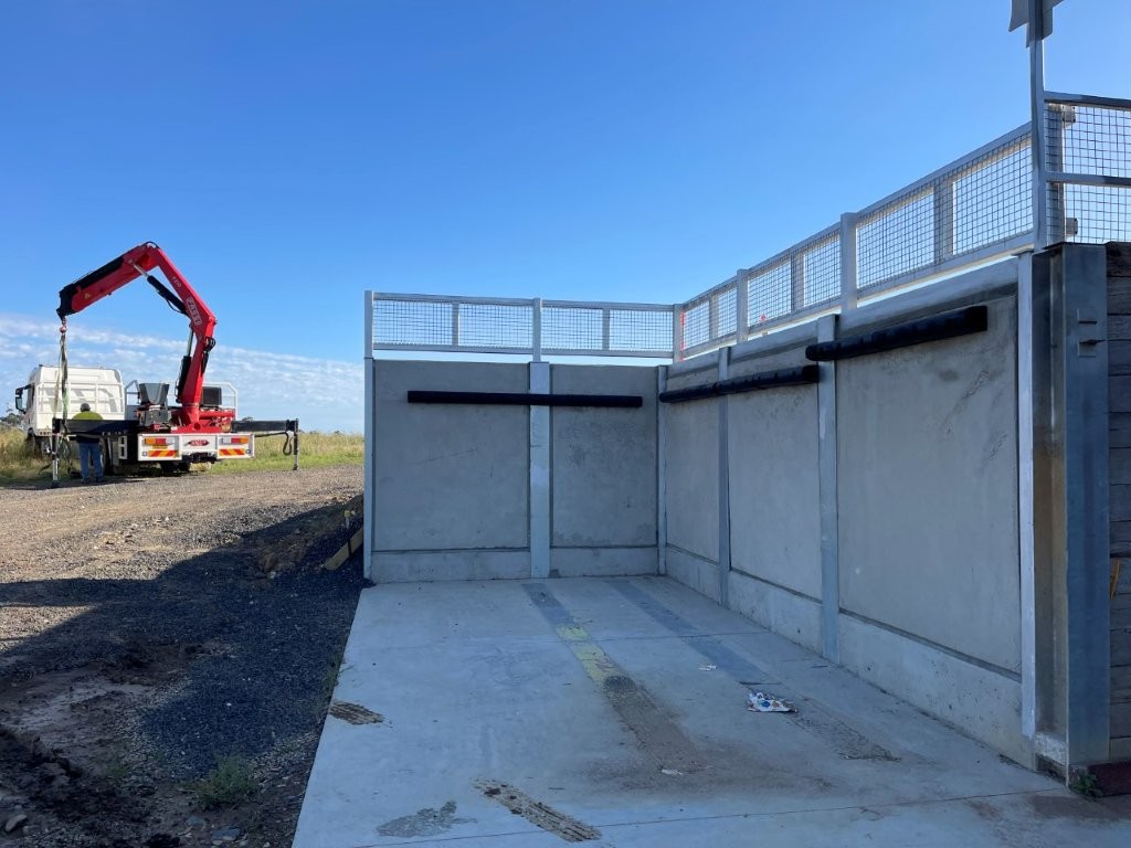
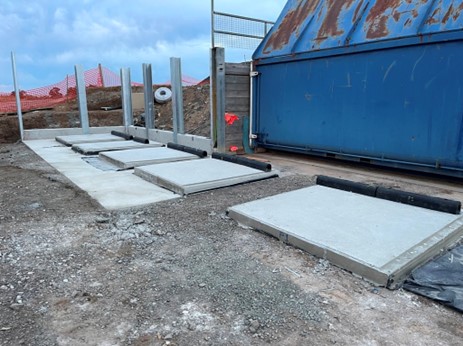
Precast Concrete Tilt-Up Wall Panels
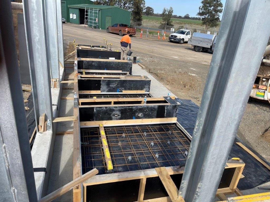
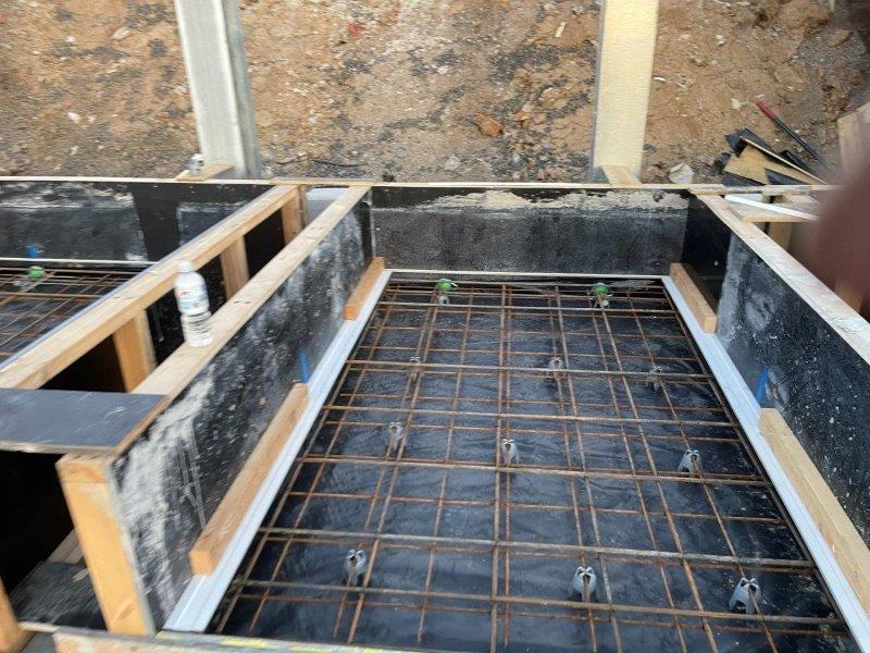
Following completion of the ground slab, the finished concrete surface provided a level casting bed for the on-site manufacture of the precast concrete wall panels. Five reinforced concrete panels, each 150 mm thick, were cast horizontally on site. The formwork shutters previously used to construct the concrete upstand were re-used as edge shutters for casting the panels.
RMD Civil Contracting constructed the panels and subsequently assisted with their installation. Local crane contractor Seymour Crane Service was engaged to lift and tilt the panels from the casting bed and install them into their final position between the structural steel columns.
Related Civilvic Drawings
Precast Tilt-Up Plan Elevations & Shop Drawings
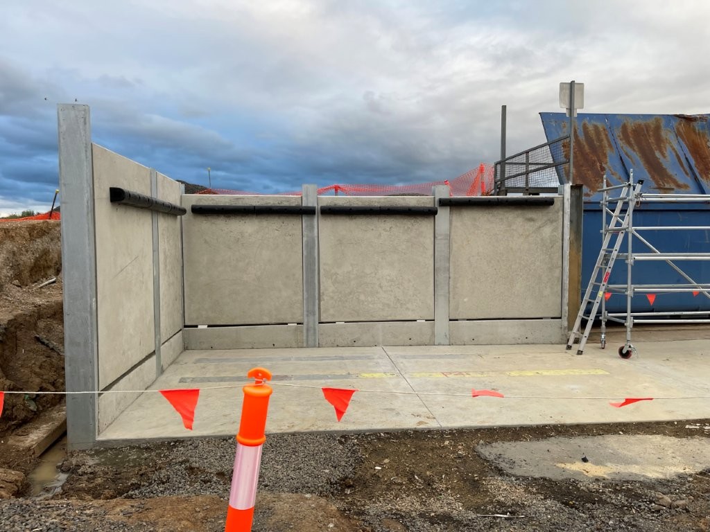
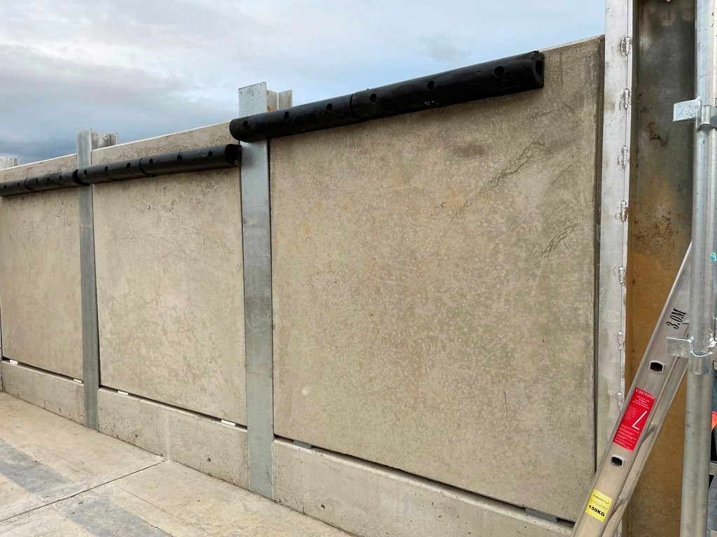
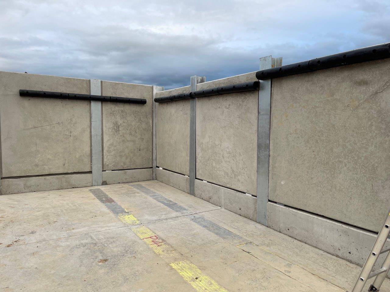
Rubber Fenders
To protect the retaining wall from accidental impact during waste bin loading and unloading operations, heavy-duty rubber fenders were installed along the upper section of the precast concrete wall panels. The fenders provide a hard-wearing impact barrier between the waste bins and the concrete panels, helping to prevent impact damage and reduce wear to the retaining wall.
The fenders are manufactured from heavy-duty fibre-reinforced rubber containing nylon and polyester and measure 1,000 mm long × 150 mm high × 150 mm wide. During manufacture of the precast concrete panels, M16 cast-in ferrules were accurately positioned to align with the predrilled mounting holes in the rubber fenders. Following installation of the wall panels, the fenders were permanently secured to the panels using M16 bolts.
Related Civilvic Drawings
Wall Protection - Rubber Fender Product Sheet
Balustrade
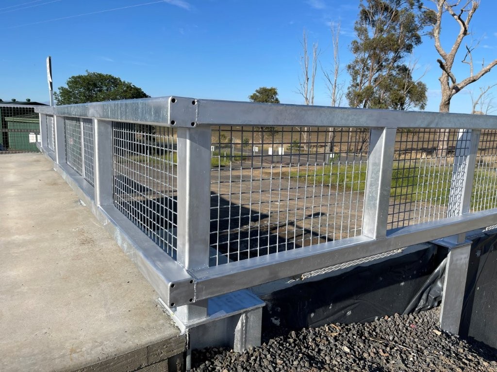
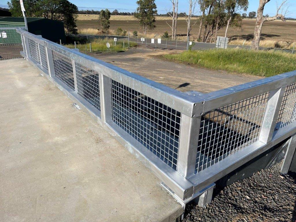
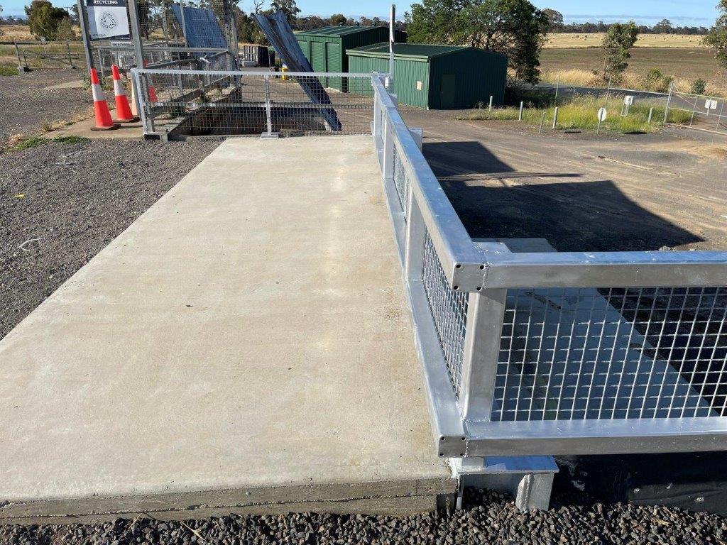
Shisham Products, based in Dandenong, were engaged to supply, fabricate and hot-dip galvanise the structural steel balustrade. The balustrade was constructed using 100 × 100 × 6 mm SHS sections. Local steel fabrication contractor RBM Steelworks was engaged to undertake the on-site welding works.
Following completion of the backfilling works behind the wall panels, the balustrade posts were site-welded to the tops of the structural steel columns. The horizontal members were then site-welded to the front face of the posts, providing a continuous protective barrier along the upper edge of the retaining wall. Galvanised steel mesh infill panels, constructed from 50 × 50 × 4 mm mesh, were site-welded to the rear face of the balustrade to provide a secure and neat finished appearance.
Related Civilvic Drawings
Balustrade Plan, Section & Shop Drawings
Fabrication Drawings
Civilvic prepared all fabrication drawings in-house, enabling the various components to be accurately fabricated and installed on site while minimising the potential for fabrication and installation errors. Civilvic's drawings included the reinforced concrete panels, structural steel columns, balustrades, skid plates and cast-in angles.
Column & Cast-In Angle Shop Drawings